New edition of ISOCoatedV2 in M1 in sight?

Even almost 9 years after the introduction of the successor colour space PSOCoatedV3, ISOCoatedV2 / FOGRA39 is still the most widespread colour space in Europe. We at Proof GmbH count around 200 jobs from time to time for the German Printing and Media Industries Federation, among others. In the last count, proofs in ISOCoatedV2 accounted for around 68% of all proof jobs at our company. This is a clear sign of the continued widespread use of the colour space.

ISOCoatedV2: From the classic colour space to the beacon of the industry

In addition to the print proofs for offset printing on image printing paper, numerous other applications also come to mind: ISOCoatedV2 is also used for many other, non-standardised or less standardised printing processes and is used as an exchange colour space: From digital printing in exhibition stand construction to packaging printing in flexo and gravure printing: almost all major players in the market rely on the power of ISOCoatedV2.

At the Fogra 2024 colour management symposium in Munich, we heard a lot about how companies and large print service providers from printing processes other than offset printing also rely on ISOCoatedV2 as a colour space reference for their applications. They are virtually following ISOCoatedV2 from the “master standard” and simply orienting themselves to the “largest ship in the colour space sea: ISOCoatedV2”, which is well established among all players in the market such as agencies and designers. Over the last few years, this has turned a successful colour space into a de facto standard.

Updated and future-proof? ISOCoatedV2 is “growing up”

It is therefore not surprising that there has been a call to provide the less popular PSOCoatedV3 with a modernised older brother: An updated FOGRA39/ISOCoatedV2, which, at the age of almost 18 years, can leave the most important legacy issues behind in order to perform its lighthouse function even better as a renewed replacement colour space.

The advantages of a new ISOCoatedV2 in M1:

  • Adaptation to the new measurement condition M1 in force since 2015 and the new standardised light D50 in accordance with ISO 3664:2009
  • Conversion of the old GDMI Gretag-Macbeth measuring base to the new XRGA for better comparability of measured values and higher precision
  • This improves process control thanks to updated H values for full tones for cyan and magenta
  • Retention of the white point of LAB 95/0/-2 and the proof on papers with few optical brighteners (OBA)
  • Classic ISOCoatedV2 proofs would still be valid, but with the new ISOCoatedV2 M1 printing condition, “new” proofs could produce more consistent and better results
ISOCoatedV2 / FOGRA39 Relaunch in M1?

Jürgen Seitz from GMG already presented this outlook at the last DPWG meeting of Fogra in Aschheim and already presented a new FOGRA39 data set in XRGA M1 for discussion. We in the proofing sector could then print a classic FOGRA39 proof on low-lightener proofing paper and measure it with M1 (like all new standards) – with the best results. However, the overriding aim is not so much to update an existing printing condition, but rather to make an exchange colour space fit for the future. The proposal for the profile name of the ICC profile for the ECI: ISOCoated_v2_M1.icc.

What speaks against an updated ISOCoatedV2?

Colour management expert Jan-Peter Homann from Berlin points out: “Users use characterisation data for separation, proofing and controlling the printing process. However, a new characterisation data set would not be suitable for print process control due to the white point with M1. The small but still existing differences to the classic ISOCoatedV2 FOGRA39 data set could unsettle users and make communication between prepress, proof and print more complicated and cause misunderstandings. Jan-Peter Homann therefore fears that an updated ISOCoatedV2 would be ignored by the market.

Sphere Head Spectrophotometers and Specular Component explained

Specular Component Spectrophotometric Measurement SCI / SPIN and SCE / SPEX explained

Different surfaces can influence both the colour and the appearance of objects. A colourful and glossy object will usually appear more saturated to the eye, while a similar object with a matte, diffuse surface will appear duller.

If you form a glossy, a semi-matte and a matte surface from the same black plastic, the glossy surface will often appear blackest, while the very matte surface will appear much lighter. The same effect can be reproduced with film lamination of prints: a glossy laminated dark blue or black appears more saturated and darker, a matt laminated black becomes lighter and greyer to the human eye due to diffuse light refraction.

Humans perceive the colour of objects through the light reflected from them, and different surfaces reflect light differently. In general, therefore, there are two ways in which light is reflected from an object: The specular and the diffuse reflection.


Specular and diffuse light reflection of matt and glossy objects

Specular reflection

Specular reflection occurs when light is reflected from the light source at an equal but opposite angle. Simply put, you can think of it as a ball bouncing off a smooth floor and bouncing back at the same angle. This reflection occurs mainly on objects with shiny, smooth surfaces.

Diffuse reflection

If, on the other hand, the reflected light is scattered in numerous different directions, we speak of diffuse reflection. This reflection occurs on objects with matt and irregular surfaces. A ball would bounce off such a surface – for example, an irregular floor consisting of numerous pyramids of different sizes – sometimes at one angle and sometimes at a completely different angle.

Spectrophotometers with an integrating sphere

Today, when colour and gloss are to be evaluated in global supply chains and on different surfaces, this is often done with sphere head spectrophotometers such as the KonicaMinolta CM-26d, with which we at Proof GmbH have also measured the semi-matt and matt free-colour CIELAB HLC Colour Alas XL. With the d:8° geometry and the integrated 60° gloss sensor, which can handle both the SCI – “Specular Component Included” and SCE – “Specular Component Excluded” measuring modes, this measuring device can measure colour and gloss within less than a second without having to use an additional measuring device for gloss and always having to be set up and aligned again.


Proof.de: KonicaMinolta CM26d Kugelkopf Spektralmessgeraet mit SCI und SCE Messung: Messung des freieFarbe CIELAB HLC Colour Atlas XL


Proof.de: KonicaMinolta CM26d Kugelkopf Spektralmessgeraet mit SCI und SCE Messung: Displayanzeige


Proof.de: KonicaMinolta CM26d Kugelkopf Spektralmessgeraet mit SCI und SCE Messung: Beim CK-26d kann durch eine zurückschiebbare Klappe direkt in die Ulbricht-Kugel gesehen werden, und so der Messausschnitt durch die Kugel noch einmal visuell kontrolliert werden.
With the KonicaMinolta CM-26d it is possible to look directly into the integrating sphere through a flap that can be pushed back, and thus the measuring section can be visually checked and readjusted through the sphere once again.

With integrating sphere measuring instruments, the surfaces to be measured are usually illuminated at all angles and measured at an angle of 8 degrees from the vertical axis. This measurement condition is referred to as d/8 or d:8. Most of the integrating sphere measuring devices such as the CM-26d can measure with or without a gloss component as previously described.
In contrast, the 45/0 models used in the printing industry such as the X-Rite i1 Pro2 always measure without the specular reflection. The reflection of the sample surface is therefore perceived differently by the optical geometries d:8 with gloss component – SCI – , d:8 without gloss component – SCE – and 45/0 respectively.


Specular Component Spectrophotometric Measurement SCI / SPIN and SCE / SPEX explained

SCI measurement mode

To measure the true colour of an object without the influence of surface texture, the Specular Component Included (SCI) measurement mode is used. SCI mode includes both specular and diffuse reflected light and is ideal for quality control and colour quality monitoring.

  • Illuminates the sample evenly from all sides.
  • Takes into account the total surface reflection.
  • Has good repeatability and is insensitive to surface variations or artefacts.
  • Does not perceive gloss differences of the sample and therefore does not simulate visual assessment.

SCE measurement mode

The Specular Component Excluded (SCE) measurement mode, on the other hand, which excludes specularly reflected light, is used to evaluate the colour of an object to match the visual perception of the human eye. In SCE mode, a glossy surface is typically measured darker than a matte surface of the same colour; similar to how the human eye sees it. This mode is typically used in quality control testing to ensure that colour matches colour standards through visual inspection.

  • Illuminates the sample evenly from all sides, but not in the reflection angle of the measurement.
  • Excludes specular surface reflection, although usually not completely
  • Includes diffuse surface reflection.
  • Is somewhat sensitive to surface variability and unevenness.
  • Measures the colour of a surface similar to how the human eye sees it.

CIELAB HLC Colour Atlas available in the Proof.de Shop

HLC Colour Atlas freieFarbe proof.de 2

It has taken almost a year, but we are all the more pleased now: The “CIELAB HLC Colour Atlas” is completed and can be ordered in our shop. The HLC Colour Atlas is a open source, high-precision colour system based on open standards.

The CIELAB HLC Colour Atlas offers professional users of colour three decisive advantages:

  • The CIELAB HLC colour atlas is based on open, non-proprietary standards that are free of copyrights and trademarks.
  • The colour atlas with all components is available to all users free of charge online and can be downloaded, used and passed on directly.
    It is released under an OpenSource Creative Commons license.
  • The printed reference of the CIELAB HLC colour atlas impresses with outstanding precision and, unlike some commercial products, the colour accuracy is extremely high with a DeltaE00 median of 0.3 and an average DeltaE00 of 0.5. In most cases, the deviation from the ideal colour reference and colour differences between two colour atlases can be measured, but not perceived by the human eye. Each atlas is produced on our best Fogra-certified high-end proofing printer on Fogra-certified paper. Each copy is delivered with an individual, colourimetric test report in accordance with ISO 12647-7:2016 to document the colour accuracy of each individual colour atlas.

Read more

Fogra 51 and Fogra 52 Beta Proofs available

By switching to the new Fiery XF 6.1 and the use of the new X-Rite SpectroProofer ILS-30 measuring instruments, we are now able to proof the current beta versions of the new printing standards Fogra 51 and Fogra 52.

Since the current proofing profiles are available only in preliminary beta versions, the versions are of course not color binding and legally binding. Nevertheless, interested agencies and printers can get a picture of the current state of development and evaluate the coming changes of the OBA proofing papers used better match the colors of the new proofing standards.

We have created a new category in our Proof.de Store:
Fogra 51 / Fogra 52 Beta Proofs

The Fogra 51/52 Beta proofs are listed as follows:

Proof profile Coated:
PSO_Coated_v3_ECI Practice Fred15_Oct2014.icc

Proof profiles Uncoated:
PSO_Uncoated_v3_eci_Fred15-July2014.icc
PSO_Uncoated_blueish_v3_ (ECI) -Fred15-July.icc

Software: Fiery XF 6.1
Proof printer: EPSON 7900/9900
Measurement: Epson / X-Rite SpectroProofer ILS30
Measuring standard: M1 with UV

Proof Paper Coated: EFI Proof Paper 8245OBA Semimatt 245gr / sqm
Proof Paper Uncoated: EFI Proof Paper 8175OBA Matt 175gr / sqm


Proof.de Introduced new measuring technology: X-Rite SpectroProofer ILS30

Detail of X-Rite SpectroProofer ILS30 Measuring head and comparison to X-Rite Spectroproofer ILS20

With the new SpectroProofer ILS30 made by X-Rite, Proof GmbH has created the basis for automated measurements and Proof verifications according to M1 standard. Proofs with optical brighteners (OBAs – Optical Brightning Agents) can now be measured. Contrary to earlier announcements, the new SpectroProofer are also able to measure the current proofing standards as before in M0 measurement standard.

Because of the new ILS30 SpectroProofer, the layout of the Ugra / Fogra media wedge was slightly modified. For a comparison between old and new media wedge, see the image below.

Detailed X-Rite SpectroProofer ILS30 measuring head compared with X-Rite SpectroProofer ILS20
Detail Spectroproofer ILS30 front, ILS20 at the back

X-Rite Spectroproofer ILS30 Packaging

Read more

Reproduction of anaglyph images and line drawings

Anaglyph glasses - transmitted spectrum of the two foils

Already a few weeks ago we received an unusual request: The musician and aspiring art student Tobias Weh from Osnabrück experimented with line drawings based on anaglyphs and achieved very good results on the monitor. He created superimposed line drawings, which then delivered a different image when viewed through the left eye than when viewed through the right eye. The question was whether this could be reproduced better with the high color range of a proofing system than with a simple domestic inkjet printer.

Since such questions are of course very interesting at first sight, we were quickly prepared to support Mr Weh in his work. To get closer to the matter, we use an i1 Pro 2 and BabelColor Color Translator & Analyzer to measure the spectra for the two films, which are transmitted through standard anaglyph glasses.

Anaglyphenbrille - Durchgelassenes Spektrum der beiden FolienActually a very satisfactory result. By choosing two colours as printing in the spectral ranges of 450 to 500 nanometres for blue and 650 to 700 nanometres for red, it should actually be possible to achieve quite a good result.

Read more

How exactly can printing ink be measured?

For some years now, the possibilities of colorimetric measurement of printing inks have become simpler and cheaper. And so it is often believed that measuring printing inks is simple, inexpensive and, above all, highly accurate. And this also across a wide variety of brands and generations of measuring devices. Is that true?

If you look at a few studies, that does not necessarily seem to be the case. IFRA, for example, requires that when measuring BCRA ceramic tiles the colour differences between different measuring instruments should be below Delta-E 0.3. In reality, however, things looked different. In a Nussbaum study, 8 out of 9 measurements were for a Delta-E greater than 2.0; in a Wyble & Rich study, the deviations were between Delta-E 0.76 and 1.68. But why are the deviations so large?

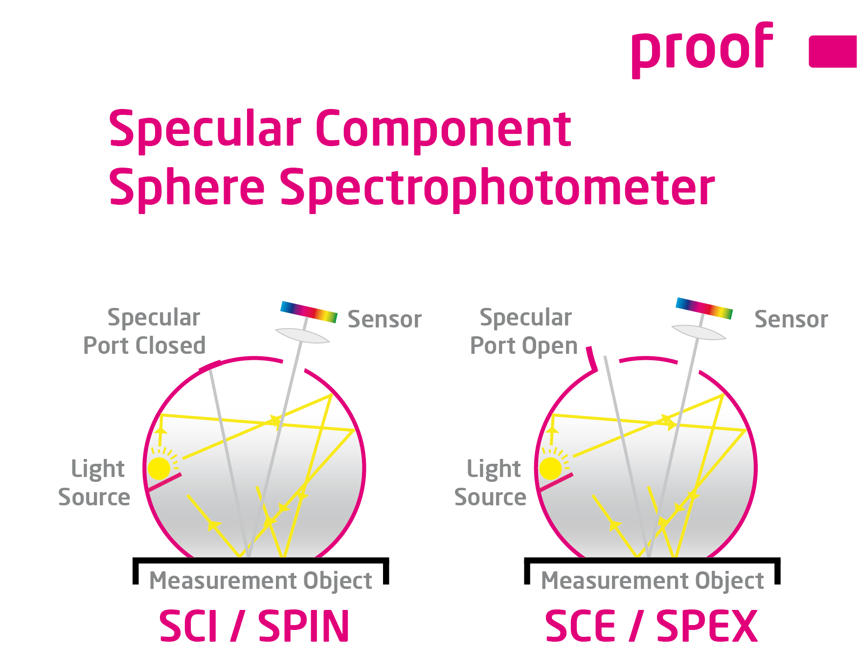
On the one hand, the measuring instruments differ in the way they illuminate the surfaces to be measured. This is important in two respects: On the one hand, measurements can vary greatly depending on the material, for example, because light is emitted and measured from only one light source onto the measuring surface. If a measuring instrument has only one lamp, which, for example, radiates at an angle of 45 degrees onto the measuring surface and whose reflection is measured, then the measurement can deviate by up to Delta-E 3.0 if you only rotate the measuring instrument about its own axis. If a left-handed person and a right-handed person measure the same tiles with the same measuring device, then just by holding the measuring device differently and by the different lighting angles of the tiles a measurement can be completely different.

The solution for this: In a measuring device, several light sources are distributed or, in the best case, the illumination is emitted directly circular at an angle of 45 degrees in order to minimize such effects.

Read more

The proof is much darker than the image on my monitor. Why?

Customers are often unsettled when they hold a proof in their hands. “The proof of the picture is much darker than the picture on my monitor. Why is that so? And what do I do now?”

There are many possible reasons for a deviation between the proof and, for example, the monitor display:

  • The monitor is not calibrated
    Only calibrated monitors can accurately display color. When I buy a cheap monitor and connect it to my computer, I definitely can’t see any real color. As a rule of thumb, only a hardware-calibrated monitor has a chance for correct color.
  • The monitor is calibrated, but the colors look different
    A monitor below 1,000 Euro cannot usually be calibrated to good color representation for the standard color space ISOCoated V2, because it has a too small color gamut. Only real proof monitors are also designed and suitable for the display of proofable colors.
  • The proof is not viewed under D50 standard light
    Especially in winter the lighting conditions are often poor. And incandescent lamps, energy-saving lamps and conventional neon tubes only provide very poor colour reproduction. Without a D50 light source, a proof cannot be evaluated.
  • The color settings in the software are wrong
    Often the image editing software like Photoshop is simply installed and used without adjustments. The selected color profiles often do not correspond to the profiles used for proofing. Apple-Shift-K for Macintosh and Control-Shift-K for Windows show you your profile settings in Photoshop.

In general, no patent remedy can be given for the correct display of proofs for the monitor. However, if a proof is provided with UGRA/Fogra media wedge CMYK V3.0 and test report, the chances are high that it reproduces the required colors very precisely. If your monitor image does not correspond to the proof, the error usually lies with you. The list of causes above can help you in troubleshooting.

Why monitor and paper don’t get along when it comes to colour.

Colour is colour, you’d think. That’s right. But have you ever tried to explain the colour of your new car or your new red wallet to a friend on the phone? You will notice that human colour recognition and the reproduction of the same in another medium is very difficult.

The same applies to computers – better: monitors, and printers – i.e.: laser printers, inkjet printers or newspaper printing or offset brochure printing.

Why is the red on a monitor different from exactly the same red printed on paper? It’s simple: put the paper in front of the monitor. The two shades of red are exactly the same. Like this. And now you’re completely darkening the room. What do you see? The red on the monitor is still red. And exactly the same red on paper? This is black now. Why is that? Very simple:

A monitor adds light, i.e. spectral components, to the existing ambient light. If you see red on a monitor, it is because the monitor actively emits red light.

And now the paper: When do you see red on paper? Exactly when white light falls on the paper, for example through a window or a lamp. And when do you see the colour red on paper?

When white light falls on the paper and the paper extracts the non-red spectral components from the white light and reflects the red light. That’s when you see the colour red.

One colour, two completely different ways of production. And this is exactly where the colour calibration and the proof start. The strategy? Fairs. And this under fixed conditions and not with the human eye, but with “incorruptible” technology.

Put simply, a monitor calibration device can measure your monitor and see exactly “how much” colour your monitor can display, and “how wrong” your monitor can display colour. And if your computer knows that, it can correct the monitor.

Another measuring device can emit neutral white light onto a paper and measure the reflected colour. Depending on the printing process and paper, the ink looks completely different, but the meter again sees “how much” ink the print can represent and “how wrong” the print represents ink. And if your computer knows this, it can correct it. And:

If the computer knows the colour representation of the monitor and printer, it can correct and adjust the representation so that both correspond to the same colour. Of course, this only works if the colour and brightness of the light that illuminates the paper is also known and standardized.

And how does the proof work? Very simple:
If a computer also knows that the final printed product is to be printed in offset on an image printing paper, and it knows the colour representation of this printing process, then it can simulate this on a monitor and on an inkjet printer.

On the monitor, this colour-accurate representation is a so-called “soft proof”, the colour-accurate preview of the subsequent print on the inkjet printer is called “Proof” or “Contract Proof”.

This inkjet printing must be very precise and meet the highest demands in gamut and colour simulation. And since the image processing technology, colour matching calculation and measuring technology behind it is not very cheap, proofs are still mostly “expensive” inkjet prints. Due to new printing systems and inexpensive and better measuring technology, however, prices have also fallen significantly here in recent years.

Which RGB working colour space is suitable for colour-consistent work?

Comparison between eciRGB_V2 (white) and AdobeRGB 1998

In the early days of color spaces Apple and e.g. Photoshop up to version 5.5 set the monitor color space as working color space by default. But it soon became clear that a design office would be working with 10 Macs in 10 different color spaces. A neutral concept was needed.

There are many RGB Colour Spaces around. In the area of print media there are currently primarily three different variants: sRGB, AdobeRGB(1998) and eciRGB_V2.

The sRGB color space is widely used in digital cameras and is the industry leader in the consumer segment. Problem for printing: sRGB is a relatively small color space, and does not cover the color possibilities of modern offset printing systems and digital printers. Since offset printing profiles such as ISOCoated_v2 have a much larger color space, it makes little sense to perform retouching in sRGB.

From our point of view eciRGB_V2, a further development of eciRGB, is optimal. This color space has been specially created for use in the printing sector and offers some strengths:

  • It covers the colors of all modern printing color spaces (offset, gravure, web offset, newspaper), but is not much larger and therefore does not give away any resolution.
  • Equal shades of red, green and blue result in neutral shades of grey
  • Between 0/0/0 and 50/50/50 there is roughly the same distance as between 50/50/50 and 100/100/100.
  • The white is 5000 Kelvin and the gamma is 1.8 Kelvin.

The eciRGB_v2 color space can be downloaded free of charge from the pages of the European Color Initiative (ECI).

The AdobeRGB 1998 color space, which has been widely used by Adobe since Photoshop 5.5 and today in all parts of the Adobe product range, is also well suited for the printing sector, but works with a gamma of 2.2 and is designed for degrees of whiteness from D50 to D65. All common print color spaces can also be well mapped in AdobeRGB 1998. You can find Adobe documentation on this color space here.


Softproof – opportunity or risk?

Softproof means: The correct color display of a printed product on a monitor. Both a standardized print, e.g. according to process standard offset printing, can be simulated – e.g. a later offset print according to ISOCoatedV2 can be simulated correctly in colour on the screen – and the output on digital terminals such as LFP systems in advertising technology.

From a technical point of view, soft proofs are now well controllable. The monitor technology is advanced enough to provide excellent displays with a high color gamut and consistent illumination even for a few hundred euros. For example, monitors in two branches of a company can be coordinated in such a way that the result displayed on the monitors corresponds exactly to each other at both locations, i.e. one image editor in Hamburg and one in Munich can talk about retouching the same file.

The problem: The fact that the two monitors emit the identical color and light result can be precisely controlled. The fact that the colleague in Hamburg is looking at the foggy Alster lake at a northern window, while the colleague in Munich moved the monitor to a southern window in the direction of the Isar river in sunshine, already shows the problem: The environment variables under which the softproof is viewed are not identical.

It is even more difficult when the soft proof is to be used in the pressroom to coordinate the production run. Many companies such as JUST offer modern solutions that can provide a soft proof directly at the press. However, the problem remains that the soft proof should be considered to be less than 10% away of the brightness of the press. While 2000 lux brightness was previously the standard for printers, JUST now writes: “The comparison of soft proofs on monitors with prints and hard proofs is regulated in accordance with ISO 12646. The light conditions basically correspond to ISO 3664, but the brightness must be adjusted to the limited luminance of the monitor, which ideally is > 120 cd/m². ”

Two scenarios therefore arise at the printing press: Either the printer is “in the light” and can then match the print with a contract proof printed on paper, or it is “in the dark” and can match the print with the soft proof. The difficulty of matching paper and monitor – and these are two completely different and difficult to compare media – is compounded by the difficulty of the printer having to dim the light at the press by up to a factor of 10 to be able to match both a contract proof and a soft proof at the same workstation. From today’s point of view, this does not really seem practicable.

Conclusion: The soft proof is on the advance and will certainly sooner or later displace the classic contract proof from the market for reasons of speed and cost. However, due to the great technical lighting and haptic differences between the monitor and the illuminated sheet of paper, a widespread introduction is still a long way off. After all, anyone who has ever performed a color match on a printing press can imagine that a match to the contract proof on the one hand and to a soft proof monitor on the other hand is difficult to imagine at the same time.  The contract proof will therefore also have to remain the first choice in the near future in order to be able to carry out colour-accurate proofing of the printing result in the pressroom.

D50 is not the same as D50: Standardized light and ISO3664:2009

Since 2009, printers and proofing service providers have increasingly encountered a new D50 lighting standard: ISO 3664:2009, which defines how the new D50 standardized light, under which proofs and print products are to be evaluated, looks like. The new standard light contains UV components that address the optical brighteners that are frequently used in offset papers nowadays.

The result: next to a bluish-white glowing sheet in the pressroom, there is a yellowish-pale proof.

What is the reason for this? The standard came sort of as a surprise and was poorly communicated within the industry. All proofing substrates available from proofing service providers contain no or almost no optical brighteners – this was previously a requirement. And under the old D50 standardized light – which did not contain any UV components – the proof and production run looked identical, since the optical brighteners were not addressed in the production run. Proofing and production printing can no longer be compared on all new presses that are already equipped with light tubes of the new standard: This looks completely different, the differences in paper white are absolutely obvious.

Printers and proofing service providers have mostly replaced the old tubes with new ones. However, this is often a complex topic: The old diffusing screens, which are mounted in front of the neon tubes, had so far predominantly once again installed UV filtering in order to ensure that completely no UV components get through. If new ISO 3664:2009 tubes with a defined amount of UV components are mounted behind the diffusors, unfortunately exactly this component is missing in front of the diffusor again… So there are some extra costs for the printers.

In the meantime with M1 and the new proofing Standards Fogra51 upwards, many proofing papers with brighteners havel been launched on the market so that proof and run can be compared cleanly again in the pressroom.

Standardized light and metamerism effect

A proof is only as good as the light under which it is viewed. Just going to the window or switching on the light at dusk is useless: between December and July, between 8 am and 8 pm, between cloudy and sunny days there is a huge difference in the lighting, which makes any colour evaluation impossible. And if you switch on the light, you normally switch on a bulb with 2700 Kelvin – or even worse: an energy-saving neon bulb that somehow shines in any spectra… a disaster!

The reasons for metamerism effects (in short: that two colors look identical under one light, but completely different under another) lie in the different printing technologies. Colors that look the same under a light bulb can suddenly look very different under a neon tube.

In recent years, ink-based digital proofs have established themselves in the proofing sector. Because it is printed in ink, specially coated paper must be used, which is not in any way similar to the subsequent production run. Anyone who has ever tried to print on glossy coated paper with an inkjet printer knows: the ink never lasts! Metamerism is therefore always involved when a proof is to be compared with offset printing.

The light under which proof and production run are viewed is particularly important.

ISO 3664 regulates standardized light, which is important for viewing proofs and prints. D50 is no longer D50: The International Lighting Commission CIE has revised ISO 3664 in recent years and adapted it to today’s circumstances. If UV components used to be strictly prohibited, they are now part of the standard. In the past, the focus was on consistency between slide and print, while today monitor, digital proof and offset printing are important. Therefore, proofs must always be viewed under D50 Standardized Light, so that they are really “colour-binding” in their perception.

If you want to check metamerism effects, we recommend the UGRA colour temperature indicator. With these strips, metamerism effects can be checked very quickly and clearly.


WordPress Cookie Plugin by Real Cookie Banner